News
Nintendo FC89 Lava FC RGB Upgrade

Comprehensive Guide: Installing Lava FC RGB Board on Nintendo FC89 and Modifying the New FC Output Interface
Part 1: Modifying the FC89 for New FC Output Interface
In this comprehensive guide, we will walk you through the process of modifying the Nintendo FC89 console to accommodate the Lava FC RGB board and enhance its capabilities with a new FC output interface.
Step 1: Disassembly and Preparation
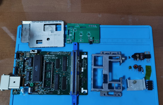
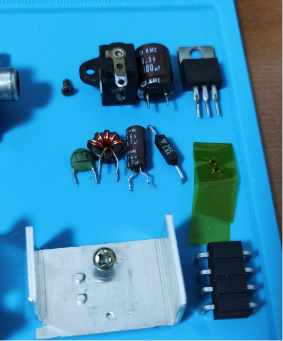
The first step in this modification is to carefully disassemble the FC89 console. Remove the mainboard and tailboard, retaining only the 12 essential components related to the power circuit on the tailboard.
Step 2: Tailboard Customization
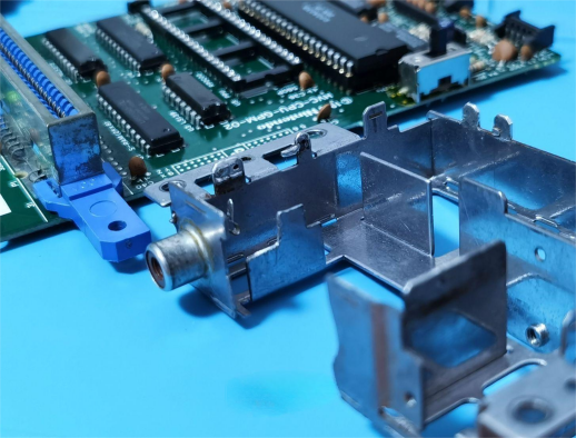
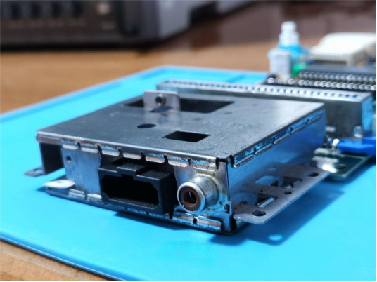
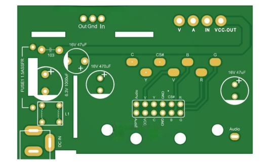
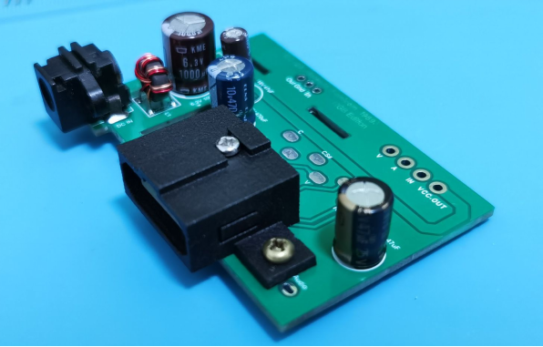
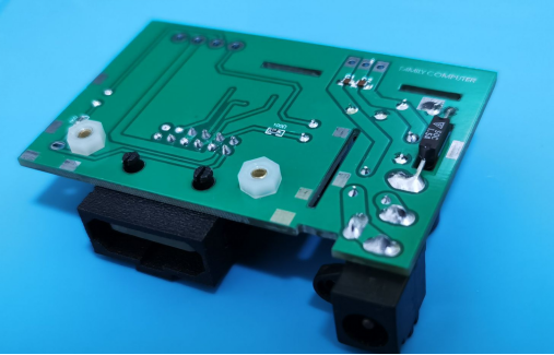
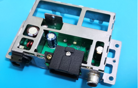
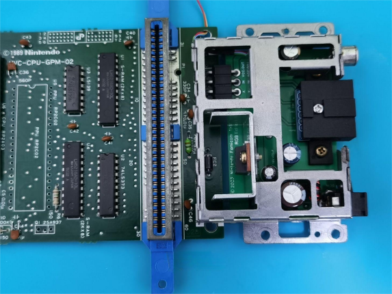
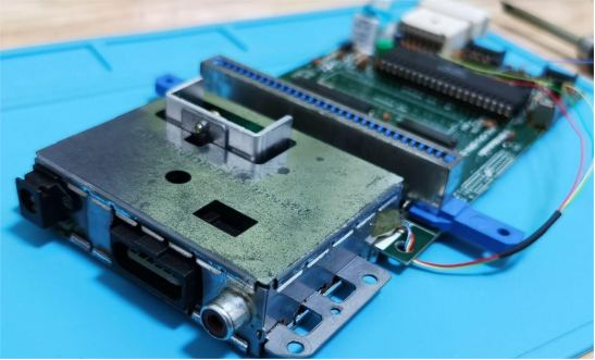
Once the tailboard is isolated, it's time to modify the rear metal frame, focusing on specific areas as detailed in accompanying images.
Step 3: Tailboard PCB Creation
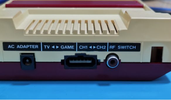
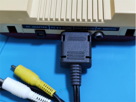
To integrate the RGB output signal and the new FC output interface, a custom tailboard PCB needs to be designed. Reinstall the 12 power components, incorporating video and audio circuit resistors and capacitors. Install the new FC 3D-printed connector. Additionally, the PCB retains the original RF radio frequency output interface pins for audio output. Carefully solder the necessary RGB output signal lines, typically four in total. Finally, secure the PCB to the metal casing, effectively completing the tailboard modification. The only remaining task is to make the necessary modifications to the rear casing.
Part 2: Adding the LAVA FC RGB Kit to the FC89 Mainboard
Step 1: Specialized PCB Design
In this section, we aim to retain the original mainboard, preserving the cartridge ejector mechanism while maximizing compatibility with the factory circuit design and cartridge compatibility.
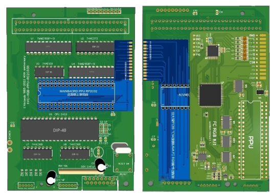
Step 2: Precise Soldering
Detailed images and instructions guide you through the soldering process. It's crucial to follow the unique sequence for soldering to achieve successful results.
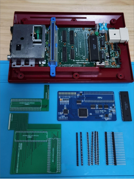
Step 3: Front Adapter Board Soldering
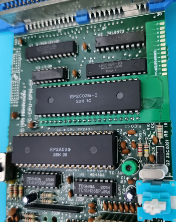
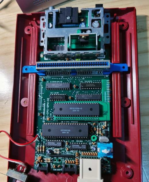
Begin by soldering the extended pin headers on the front adapter board. Pay close attention to the 20-pin header beneath the PPU, ensuring alignment with the PCB. Proper alignment is crucial to the PPU and PPU socket's correct installation.
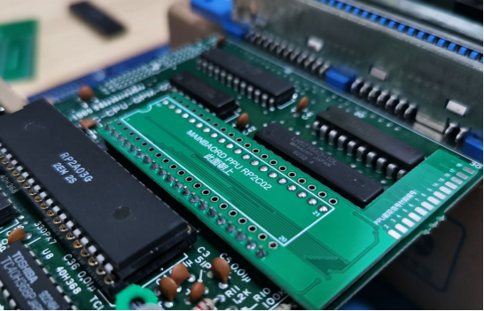
Step 4: PPU Installation
Solder the PPU socket directly or solder the PPU onto the front adapter PCB. Direct soldering is recommended as it provides ample space for the cartridge ejector to function correctly.
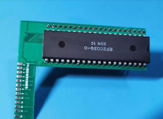
Step 5: Mainboard Connection
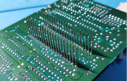
Insert the front adapter PCB with soldered components into the mainboard. Carefully solder the pins on the bottom of the mainboard, ensuring that the solder points are not excessively high. Overly high solder points may interfere with the subsequent installation of the RGB kit.
Step 6: Trimming and Installation
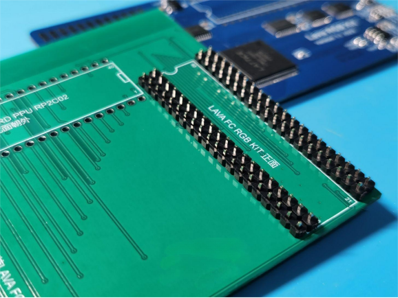
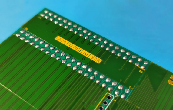
Prepare and install four plastic pins with a height of 1.2mm to 1.5mm, trimming the pin lengths to align with the 1.2mm PCB thickness to minimize connection height.
Step 7: Adapter Board Assembly
Solder the bottom adapter board onto the long pins, trimming any excess pin length for optimal results.
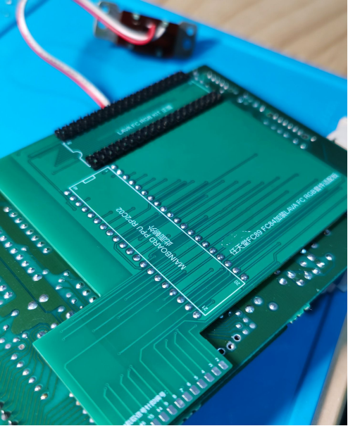
Step 8: LAVA FC RGB Kit Integration
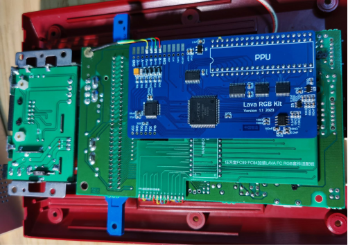
Install the LAVA FC RGB kit board correctly. Ensure that the four 1.2mm to 1.5mm plastic pins from step 6 are soldered securely. This completes the main aspect of the modification.
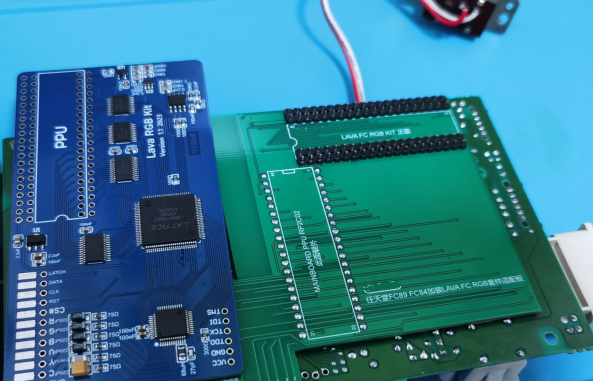
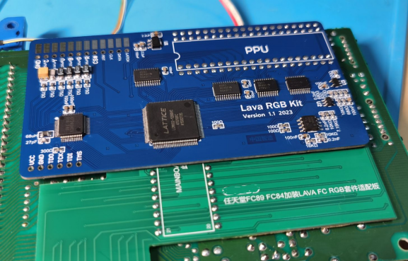
Step 9: Signal Line Connection
Connect and solder the RGBV and other signal lines from the first part's tailboard to the LAVA RGB kit.
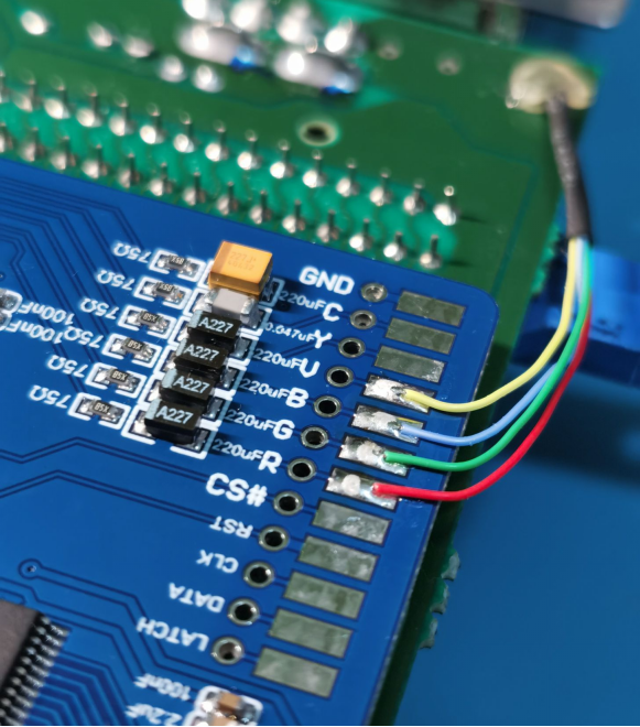
Step 10: Final Integration
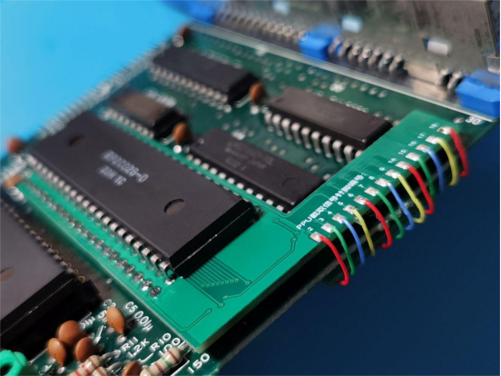
Solder the 13 PPU signal cut pins on the sides of the two adapter boards using professional signal wires and corresponding connections.
Part 3: Implementing the 3D-Printed Cartridge Ejector
With the modification process complete, the final step involves replacing the 3D-printed upgraded cartridge ejector, allowing you to enjoy your enhanced console.
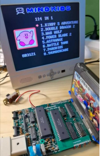
In summary, this process entails the design and production of three PCBs, 3D printing of the new FC output connector, the creation of a new cartridge ejector, and preparation of the LAVA RGB kit, pin headers, signal wires, and more. This comprehensive guide is supported by real-world test results, with the LCD television connected to the A-V signal for a thorough examination. Reference the RGB output quality, akin to the RC2C03B arcade PPU effect, through real-life images.
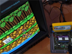
By making these modifications, you can significantly enhance your Nintendo FC89 gaming experience, preserving the console's original features while expanding its capabilities.


