News
DIY Solar Lights: Smart Outdoor Lighting Solution Ⅱ
Continuation from the previous article: DIY Solar Lights: Smart Outdoor Lighting Solution
In cold weather, high-brightness continuous mode for solar lights may not be sufficient. A 10,000 mAh lithium battery, an LED operating current of 400-500 mA, and an 8W solar panel might struggle during consecutive rainy days. Even solar lights that operate purely on motion sensing or have motion sensing combined with dim lighting (60-80 mA current) tend to stop working after a while. Solar lights with a continuous bright mode of 200-250 mA current and human motion sensing may also stop functioning after some time (4W-5W solar panels and 2200 mAh Samsung lithium batteries).
Generally, the solar panels should have voltages of 5V-6V and an LED lamp with a maximum operating current of 400-800 mA.
· Solar panels below 3W with 1,000-1,500 mAh lithium batteries are suitable for pure human motion sensing mode.
· Solar panels between 3W and 6W with 2,000-3,000 mAh lithium batteries are suitable for dim lighting continuous mode and human motion sensing high-brightness mode.
· Solar panels of 8W or more with a 10,000 mAh polymer battery, operating current of 400-600 mA, can be fully charged on a sunny day and used for two and a half nights (on the third consecutive rainy night, it may only work for three to four hours).
If you want the light to last longer, consider the following changes:
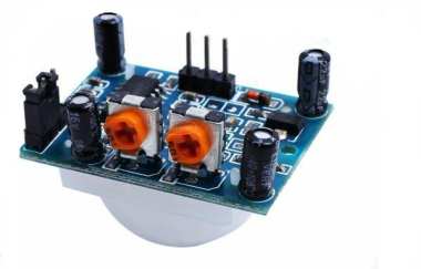
Solar light control: After sunset, when the voltage of the solar panel drops below 0.8V, the timer (or dim lighting continuous mode) is triggered automatically. If the light is outdoors, the duration is just right; if indoors, it might be too late. However, the HC-SR501 module is light-sensitive and will light up earlier.
1.RL_2 resistor: 1206 package, 1/4W power, choose 15-20 ohms to limit the current to 60-80 mA. Automatically lights up at night and turns off during the day, suitable for dim lighting continuous mode at night.
2.SR501 interface: Directly connect to the output of the HC-SR501 module. U10 is a surface-mounted SS8050 (Y1) or use a surface-mounted S8050. U9 is the constant current chip of the SR501 module, which can also be chosen with 120-380 mA.
Different working modes can be set up with the constant current chip and RL_1:
1.Dim lighting continuous + SR501 sensing high-brightness
2.Dim lighting timed + SR501 sensing high-brightness
3.High brightness for the first half of the night + dim lighting continuous for the second half
4.High brightness timed + dim lighting continuous + SR501
5.High brightness for the first half of the night + SR501 sensing for the second half
Suggestions: The total power of the LED lamp should be no less than 3W.

From top to bottom:
1.Only connect U7 (7135 constant current IC), choose between 120 mA, 150 mA, 180 mA, 300 mA, 350 mA, and 380 mA to set up high-brightness timed or dim lighting continuous mode, which will automatically turn off at the set time.
2.Only connect RL_1 resistor, 1206 package, select 1/4W power, 15-20 ohms to limit the current to 60-80 mA, dim lighting timed mode that will automatically turn off at the set time.
3.GND serves as an expansion interface, similar to B-, convenient for connecting to the HC-SR501 module.

The second type of mainboard is suitable for SR501 modules that have modified output power to 1,000 mA current (unmodified modules generally have a maximum of 400-500 mA). The SR501 interface also connects to the output end of the HC-SR501 module. U8 and U9 are two parallel surface-mounted SS8050s, reducing the heat of the transistors and not performing current limiting (constant current) for high-power LED lamps.
Suggestions: The total power of the LED lamp should not be less than 5W.


External charging indicator lights and 1K resistors make it easy to extend to the solar light housing. A 1K ring resistor can be used in series with the negative pole of the LED indicator light. R2 is the full charge indicator light, and R3 is the charging indicator light. The four welding points within the square circle are extended welding points for IN+ and are connected to the positive pole of the LED light. A two-color LED light can be used.
Each of the three types of HC-SR501 module auxiliary regions are different.


