News
DIY Linear Adjustable Power Supply Guide
If you've ever DIYed an adjustable switch-mode power supply but haven't tried making a linear adjustable power supply yet, and you're interested, you can take a look at this article.
You can start by making a voltage switching board: the adjustable power supply outputs 0–30V, with the first DC output group switching 0–10V, and the second DC output group switching 20V. Prepare the transformer secondary winding for 0–8–16–24V.
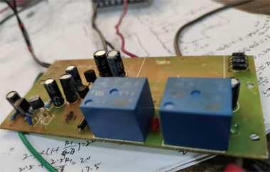
If you don't know how to make a PCB yet, you can use an old circuit board, but it needs to have space for two relays, as well as 78L05 and 79L05 positive and negative voltage regulators, so that you can power the LM358, as shown in the picture below.


Try to use as many available holes as possible; if there isn't enough space, you can solder on the back side.


Here's the situation when the first relay switches for 10V, as shown below.

Here's the situation when the second relay switches for 20V, as shown below.

You can also connect it to a control transformer to test, for example, with a secondary winding voltage of 0–6.3–12–24V.
When both relays are not activated, the output voltage measures 6.3V, as shown below.

When the first relay is activated, the output voltage is 12V, as shown below.

When the second relay is activated, the output voltage is 24V, as shown below.

Once both relays are working normally, the next step is to install the LM358 in the empty space on the circuit board.
This is the relay control circuit diagram and the winding switching circuit — 3AG1.

Done.


